Garage Network Rack with 10G Fiber

This details my 12u rack in my detached garage which has a 10G uplink to my main network
I needed some networking in my detached garage for an access point, my flight tracking setup, 3 x PoE cameras and some future additions, and instead of running multiple Cat6 cables across, I decided to just run some OM3 fiber and put a switch at the other end. This way I have 10G of bandwidth across to the house, and I can add essentially as many devices as I want. Running cables through the small breezeway which connects the garage to the house is very tough, so I only wanted to do it once. Being fiber its also removes the potential path of lightning as a few of the devices will have tall antennas.
I posted this on /r/homelab but it got removed for not being related to homelabs. As usual over moderation is rampant over there. I want to share this as I was looking for ideas on how to mount it, and I didn't really find any good full guides or posts where someone had done it outside of a commercial environment with no issues. In reality nothing will go right and it will all be a mess, like in my garage... Here is all the details
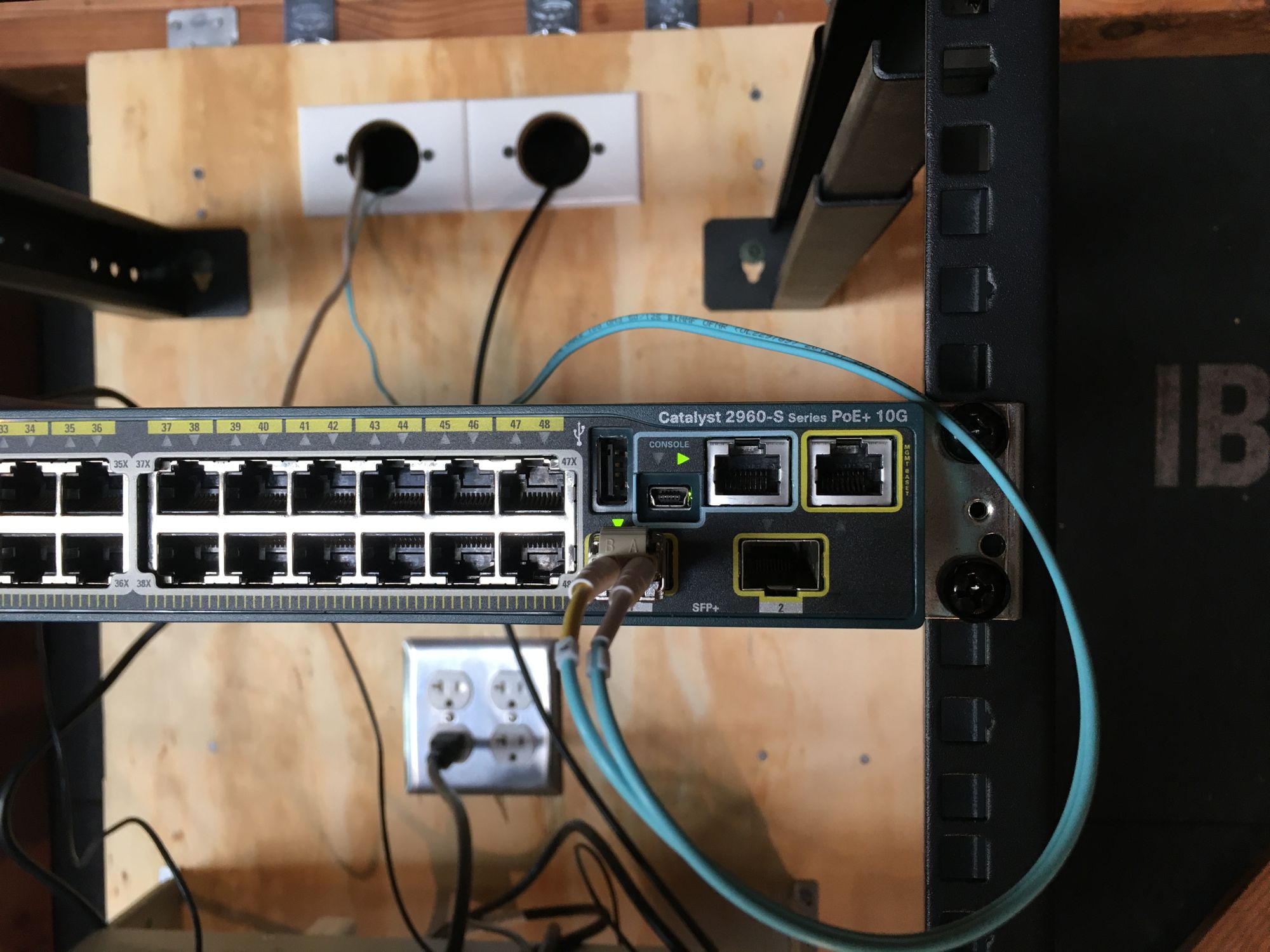
First I bought 60m of OM3 from Fiberstore, and a Cisco WS-C2960S-48LPD-L which has 2 x 10G SFP+ ports, and 48 PoE+ ports. The switch uses around 30w of power idle, so it's not too bad for the very low purchase price
First I ran the fiber from my rack. I got an LC Keystone so I could use a smaller patch cable back to the switch
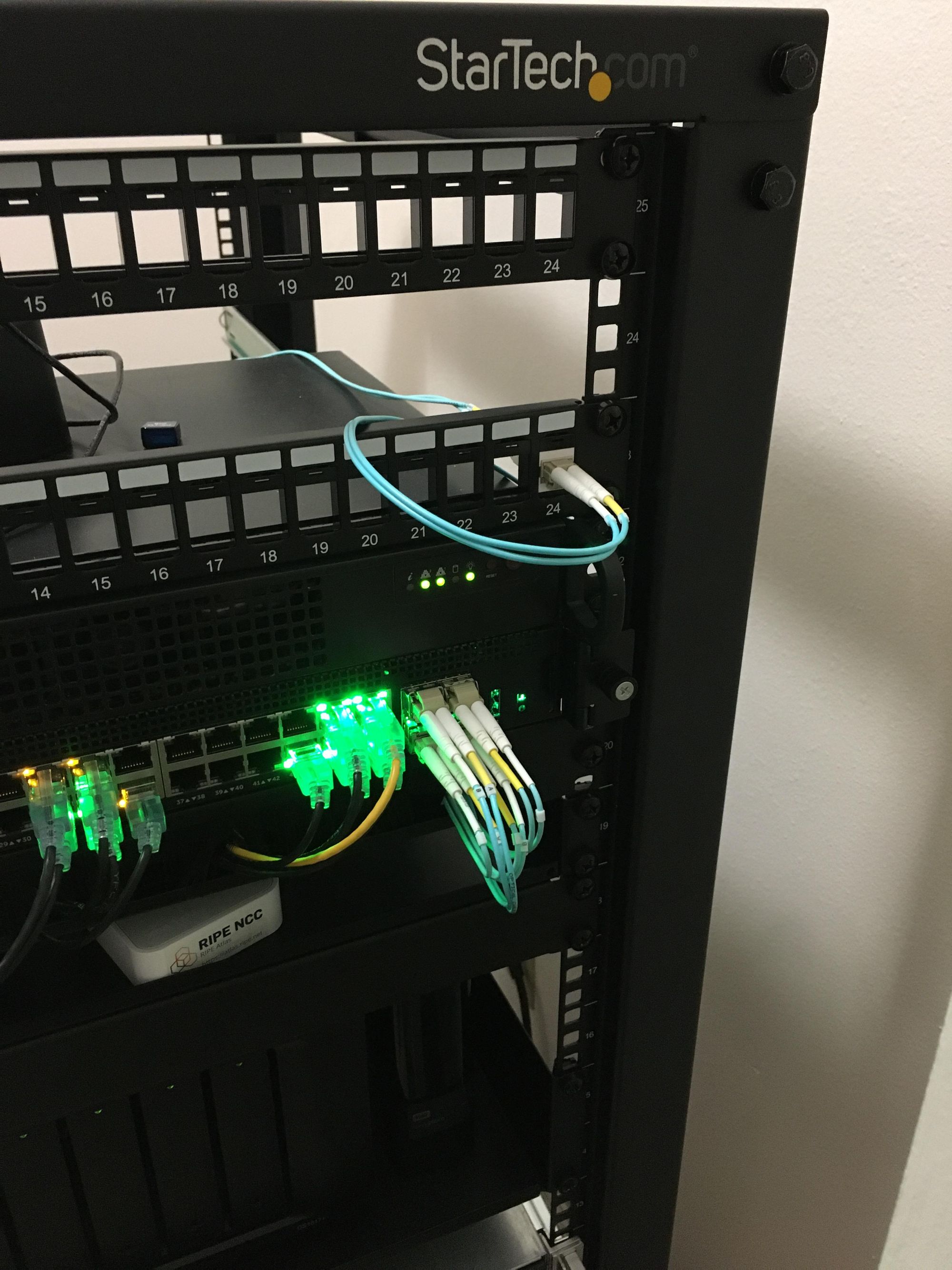
It runs into the wall where it goes up into the attic, and across into the garage. The hole into the wall is still a little bit temporary... I'll clean it up eventually. The Aqua cable is the fiber
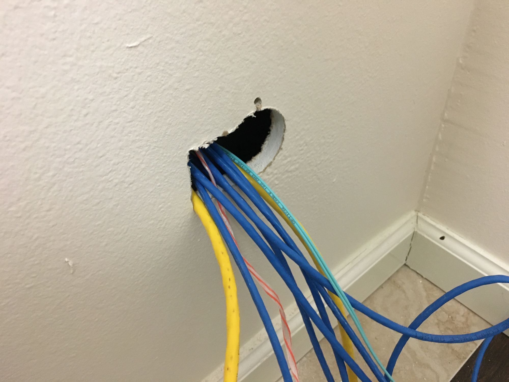
As you can see, I always keep a pull cord there to make running cables easier!
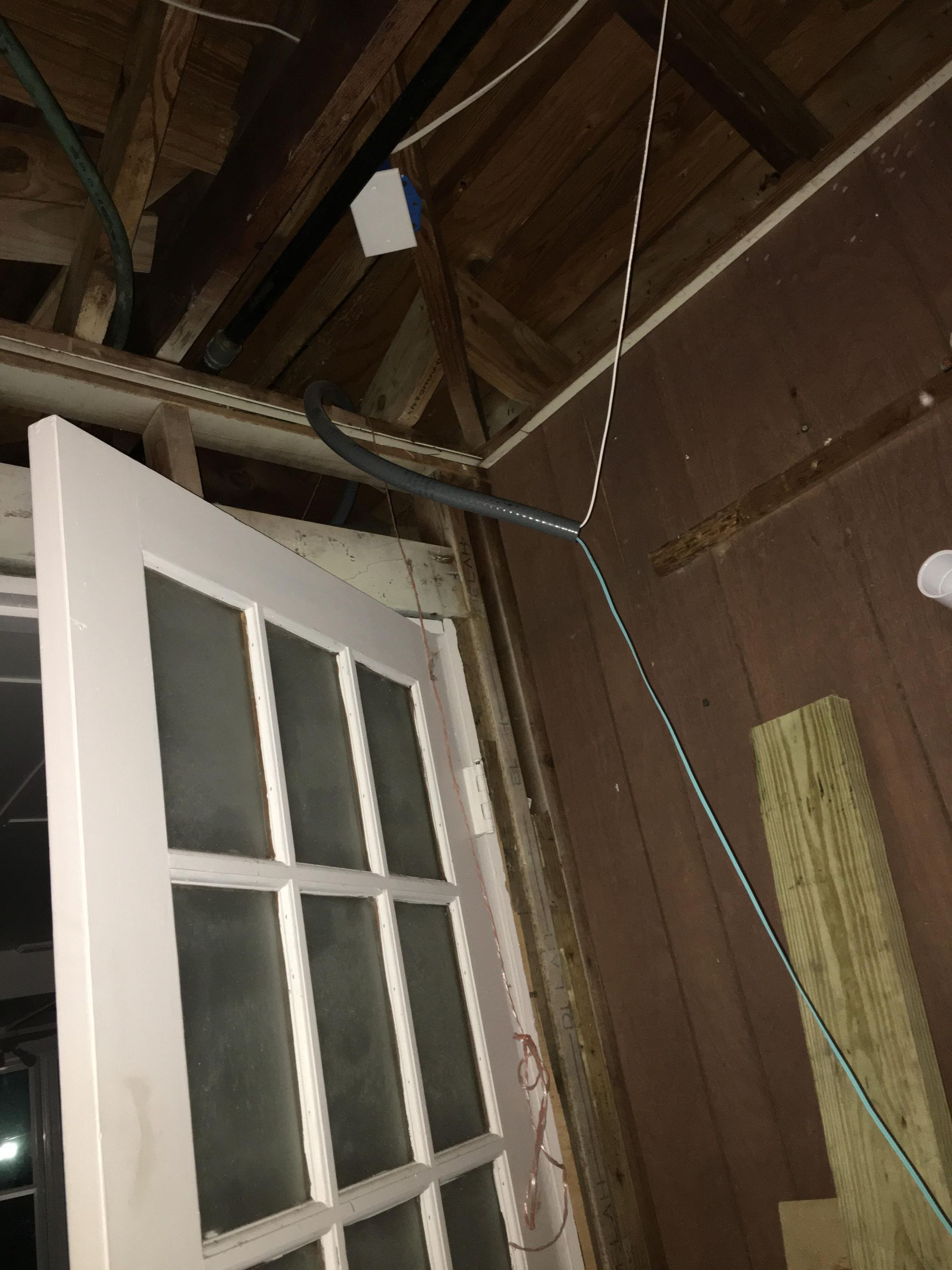
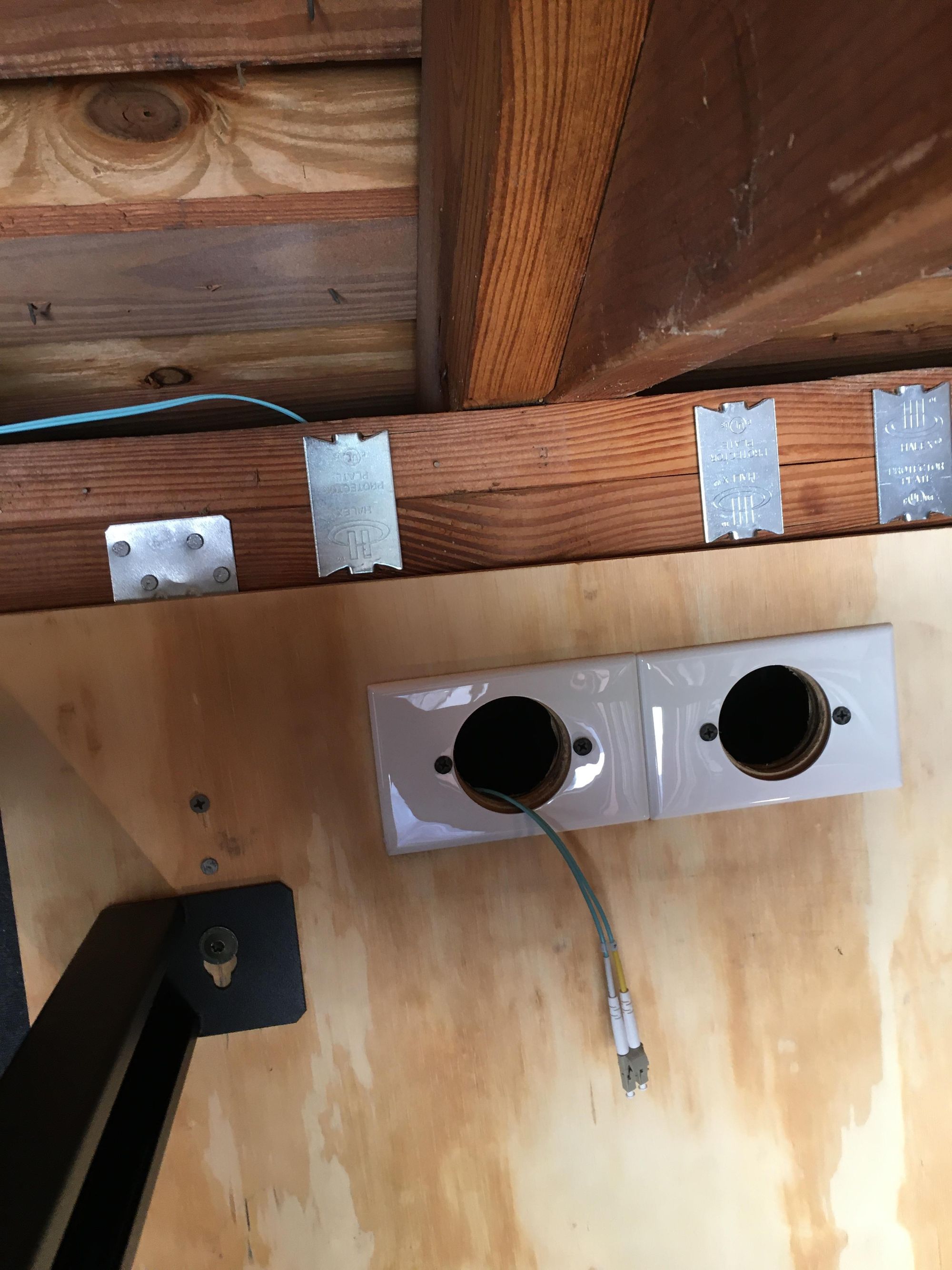
Here you can see where it comes out in the garage (Which has since been fixed up a lot, so ignore the mess) As you can see its in some conduit, I ran some 1/2 non metallic conduit across the breezeway the first day I moved in so that I could get AT&T to run their fiber across into the home, all I could find on short notice at 9:30 PM was that, so thats why I chose it
I decided to just fish this fiber through the same conduit, it worked great
Before mounting the rack I just put it on a bench to test out the connectivity. I had a spare APC SMT1000RM2U so I decided to use that
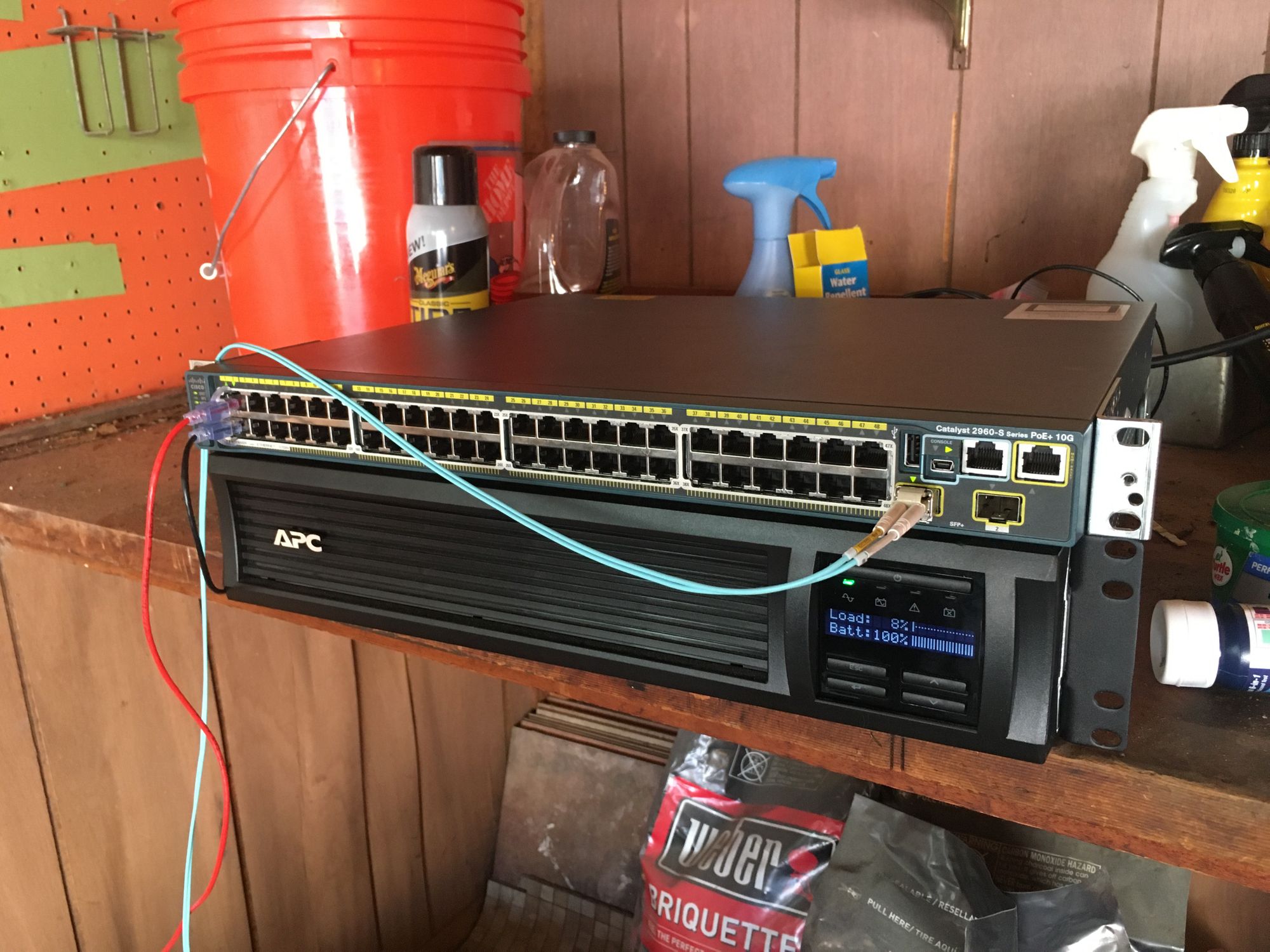
I left it here and monitored temperatures for a week and everything looked fine. On to mounting the rack
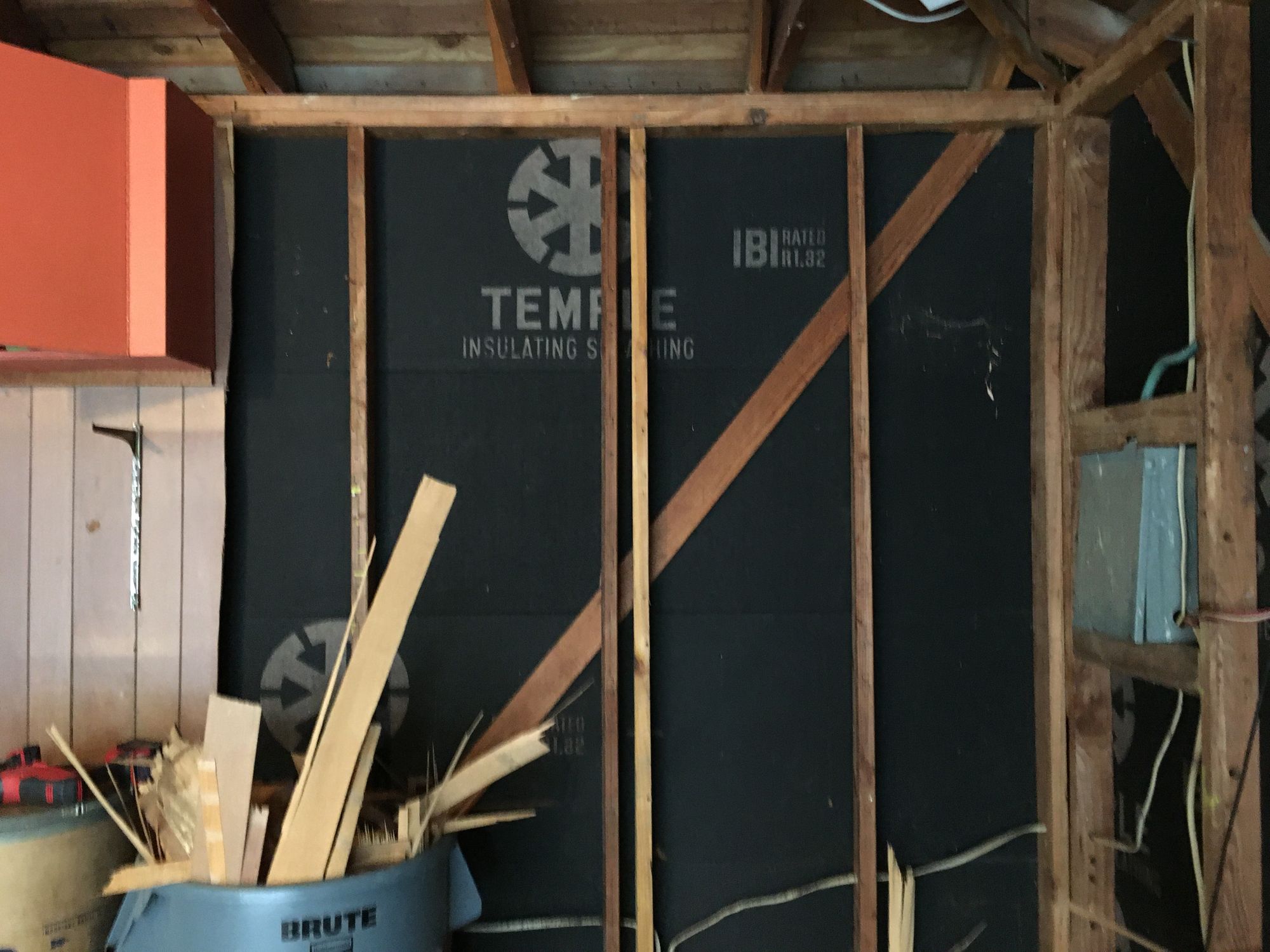
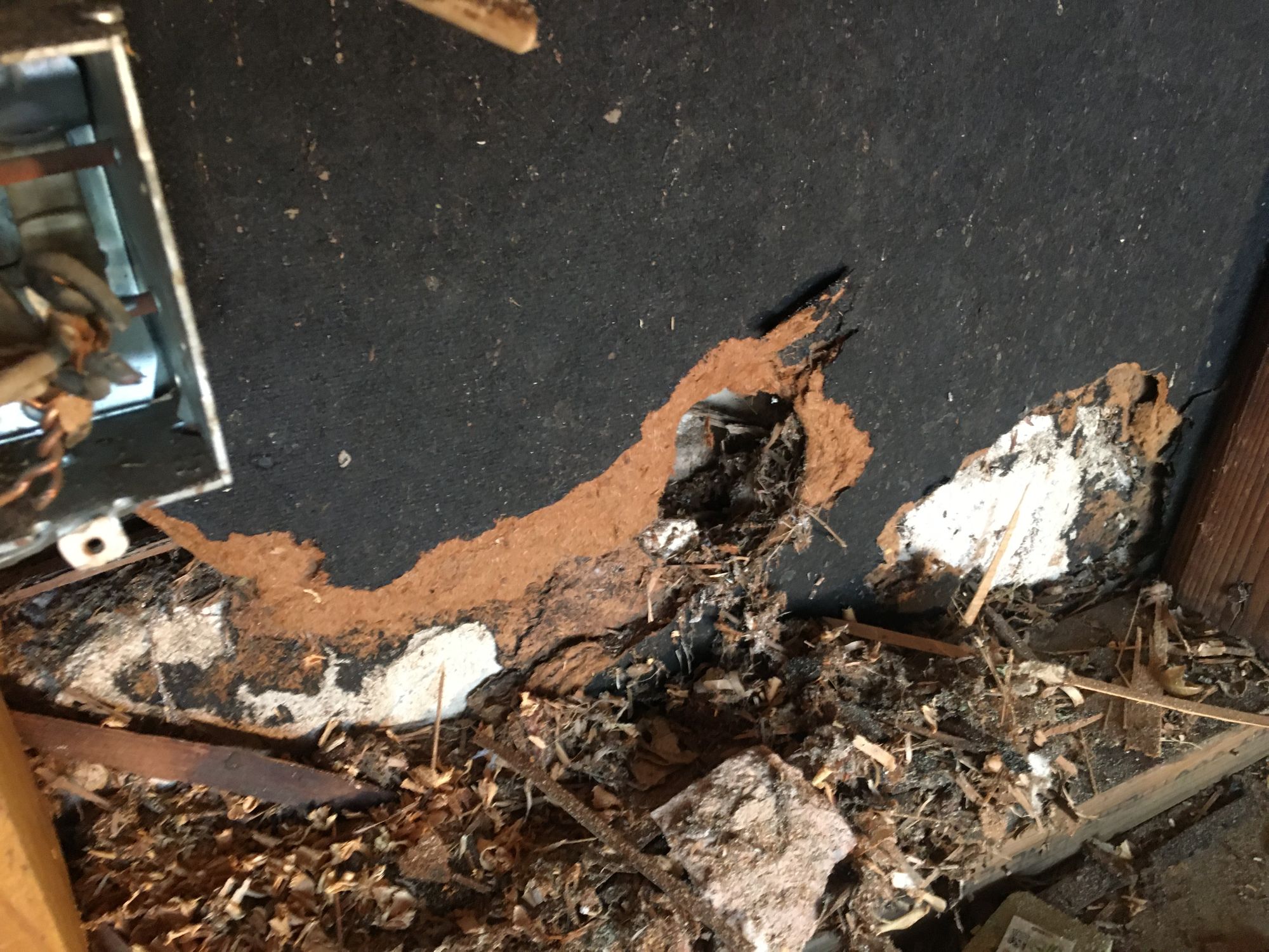
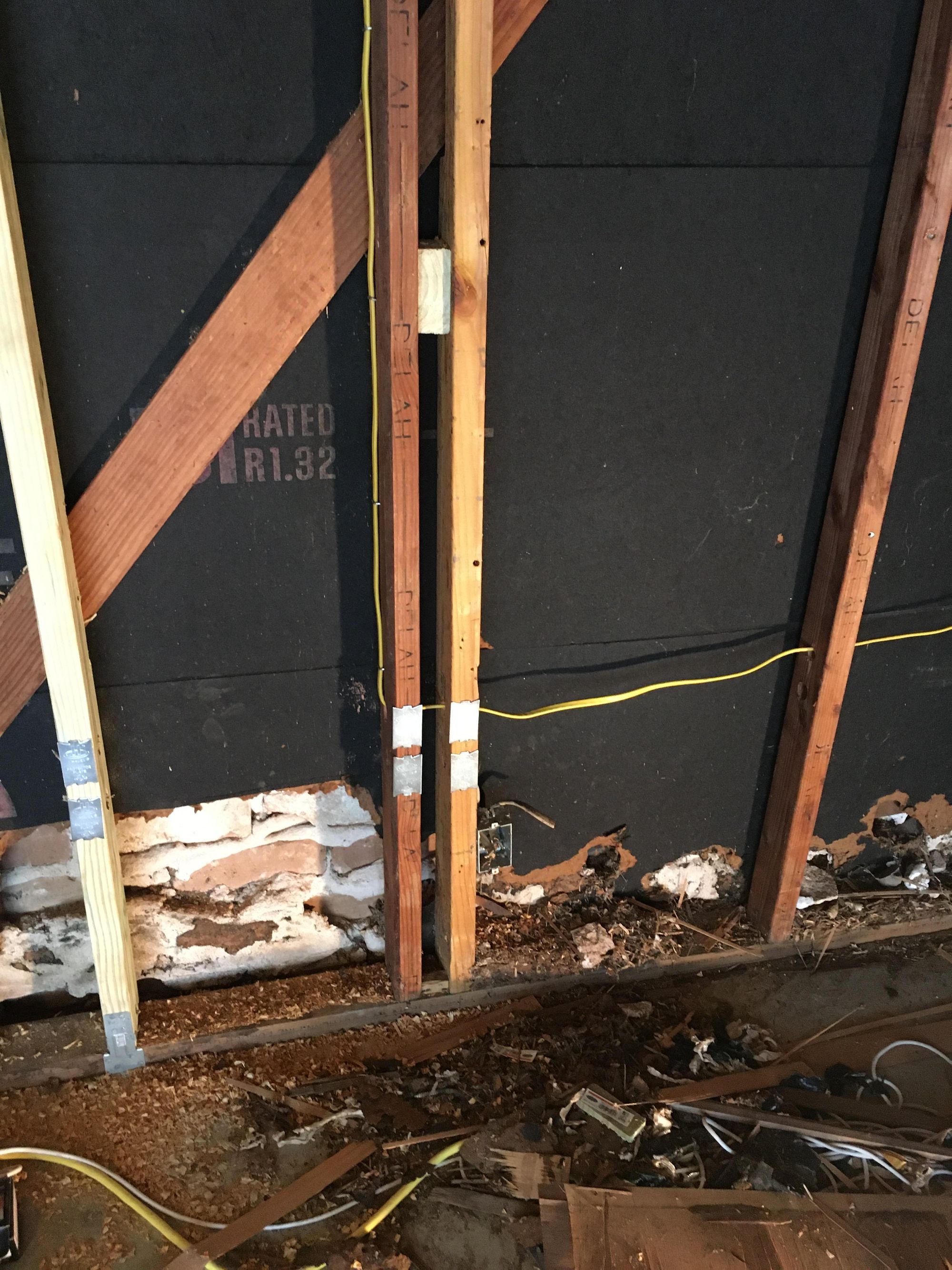
I ripped off the old wood veneer(?) that was on the wall to get a look at the studs in the location I wanted to mount. Sadly the studs were 24" on center, not 16" on center which is what the rack mounting brackets were designed for. There was also a very loose stud right next to a normal one, along with some crappy power. The sheathing was also eaten up by rats (Or something) at the bottom, it looks like its been like this a while
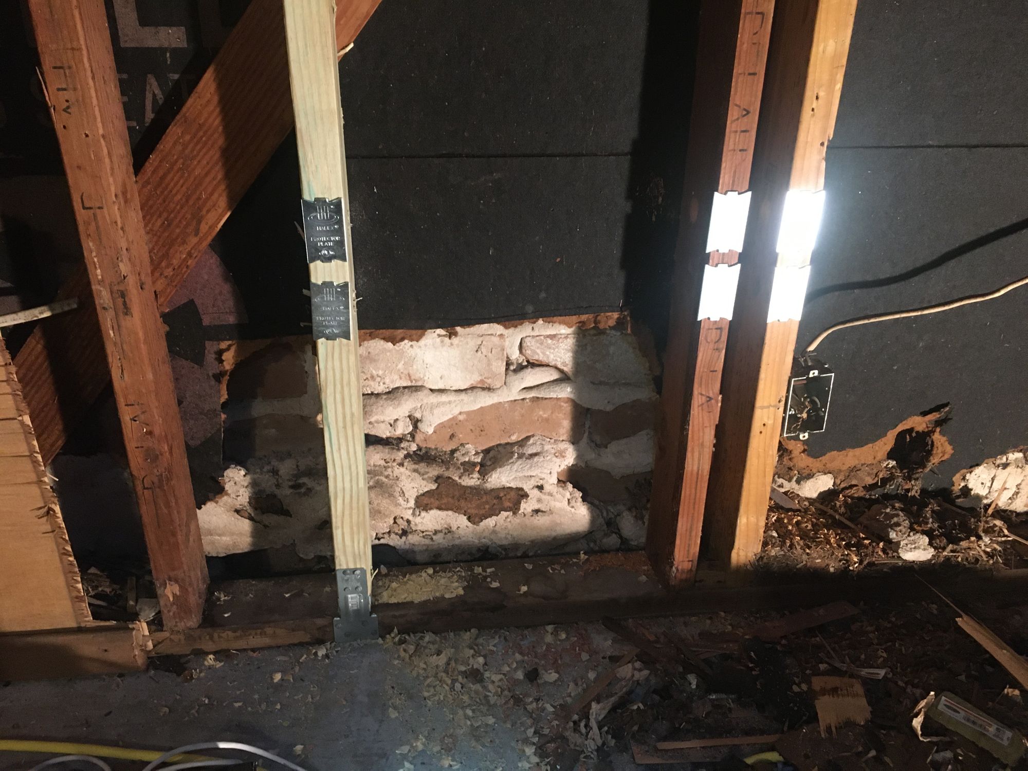
I went ahead and ripped out the old sheathing as well as installing a new 2x4 stud 16" across from the good one. This would give me the space to mount the rack. I also screwed the loose stud to the one next to it. I installed protector plates for the electrical. This was one of the first DIY jobs I took on, so my skills were a little rusty, I'm sure I could do things a little neater now, but its all functional
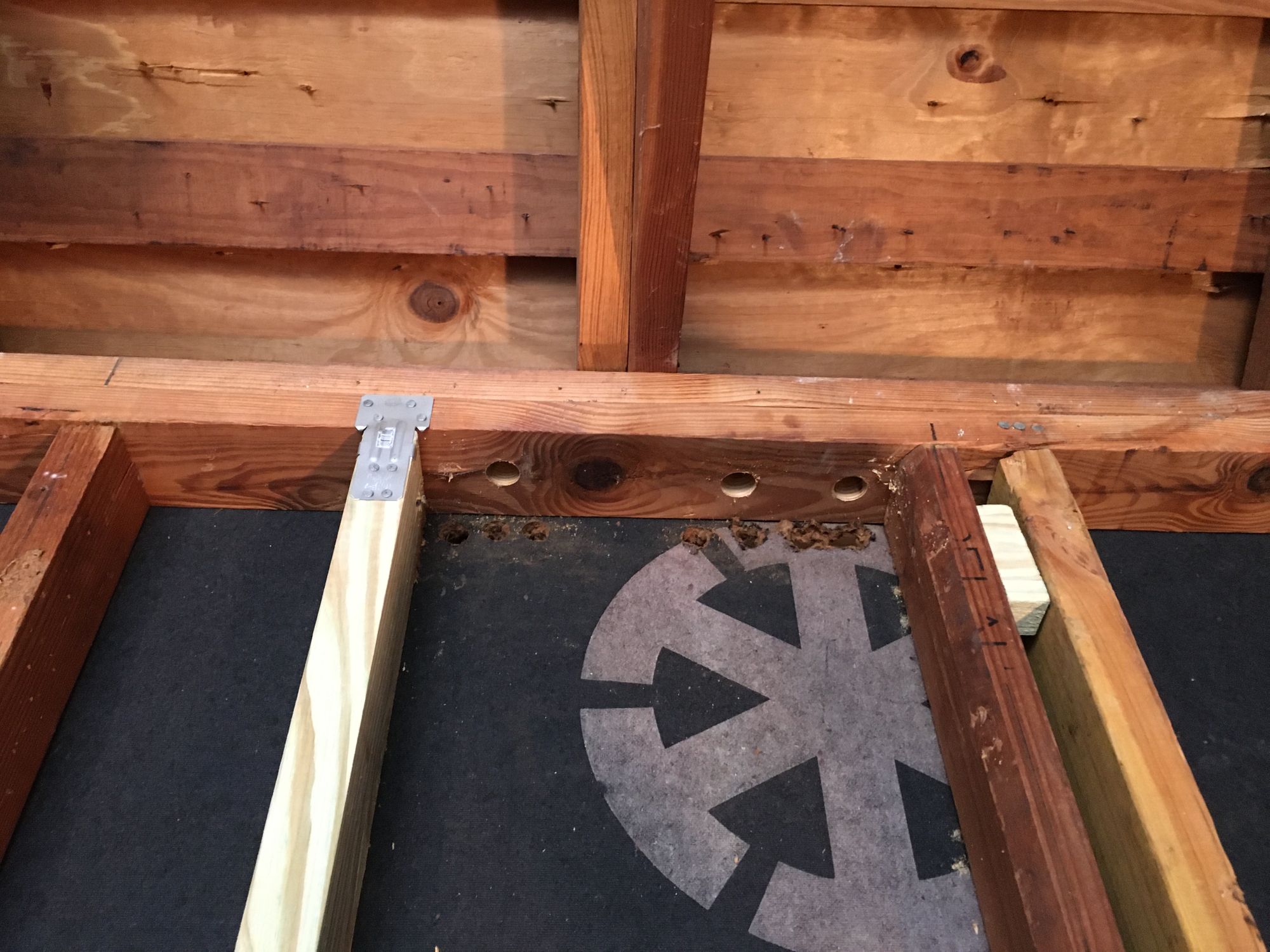
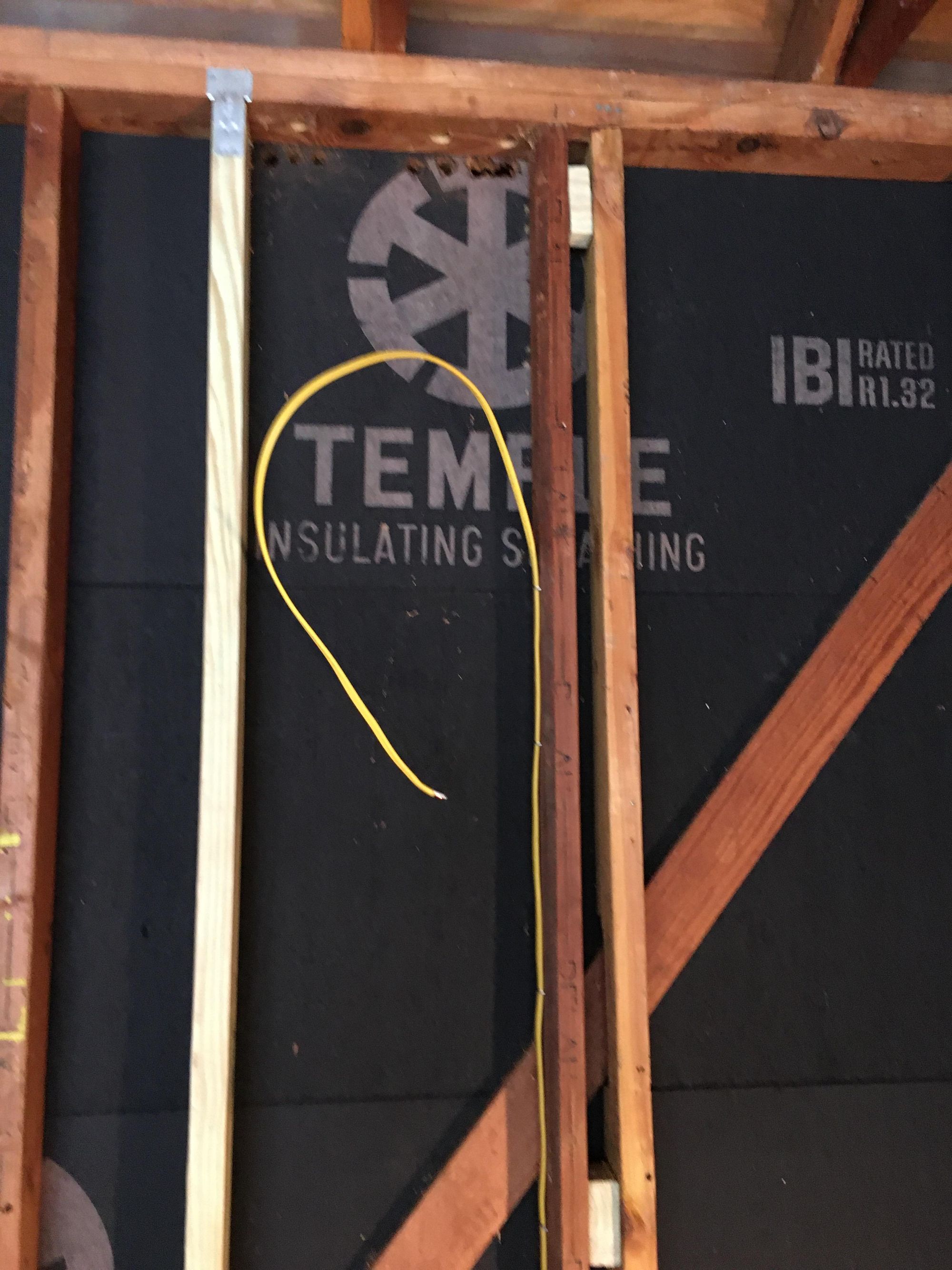
I drilling some holes in the top plate to run cables through
Then I ran a new dedicated 20a circuit up for the rack. I am swapping in a new much larger panel so it was a no brainer giving it a dedicated circuit
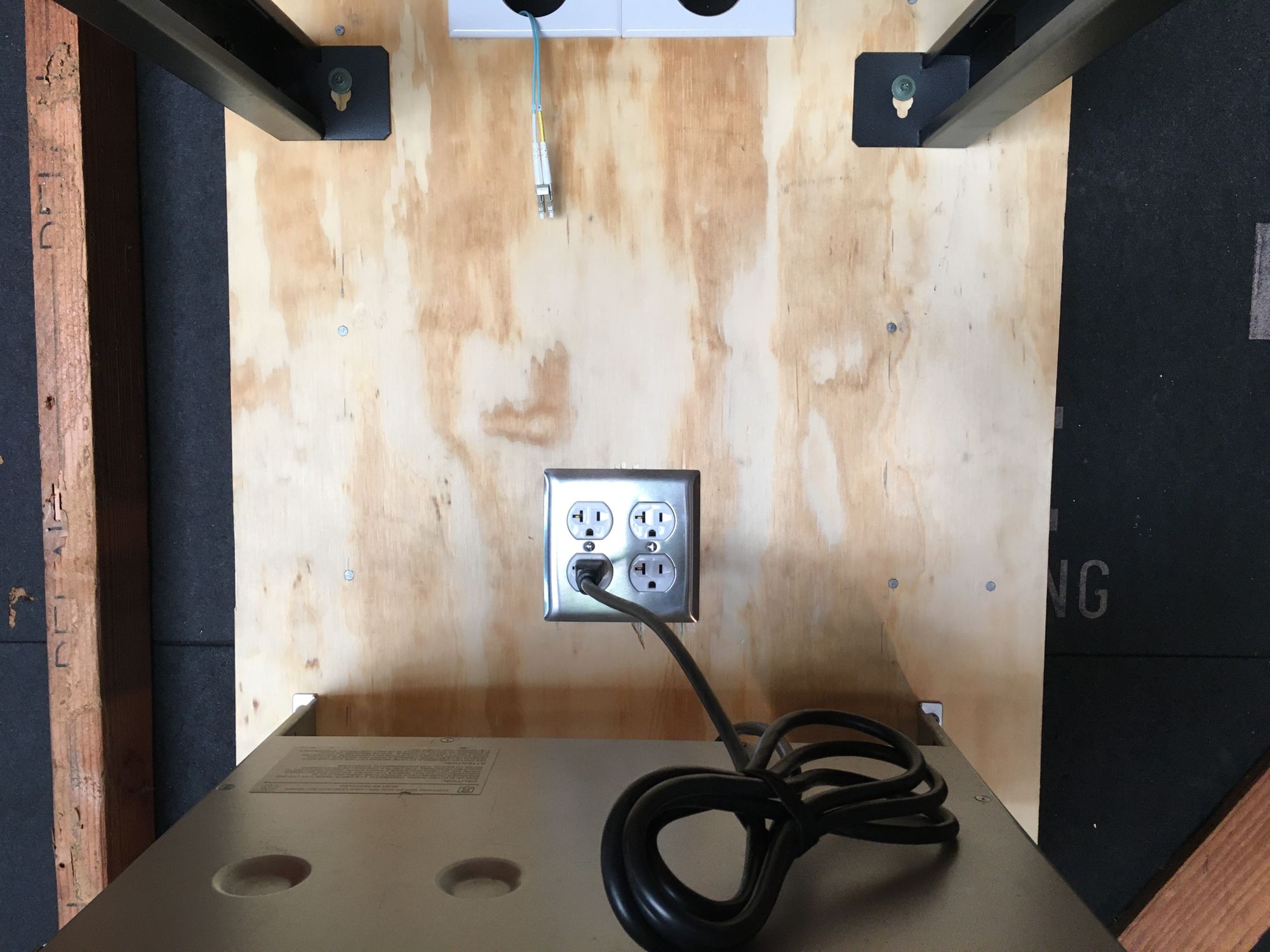
I installed some 15/32 plywood on the wall and attached it with some screws. I cut a hole for an old work electrical box. I started cutting the hole with a very aggressive blade which chipped the wood a little bit, next time...
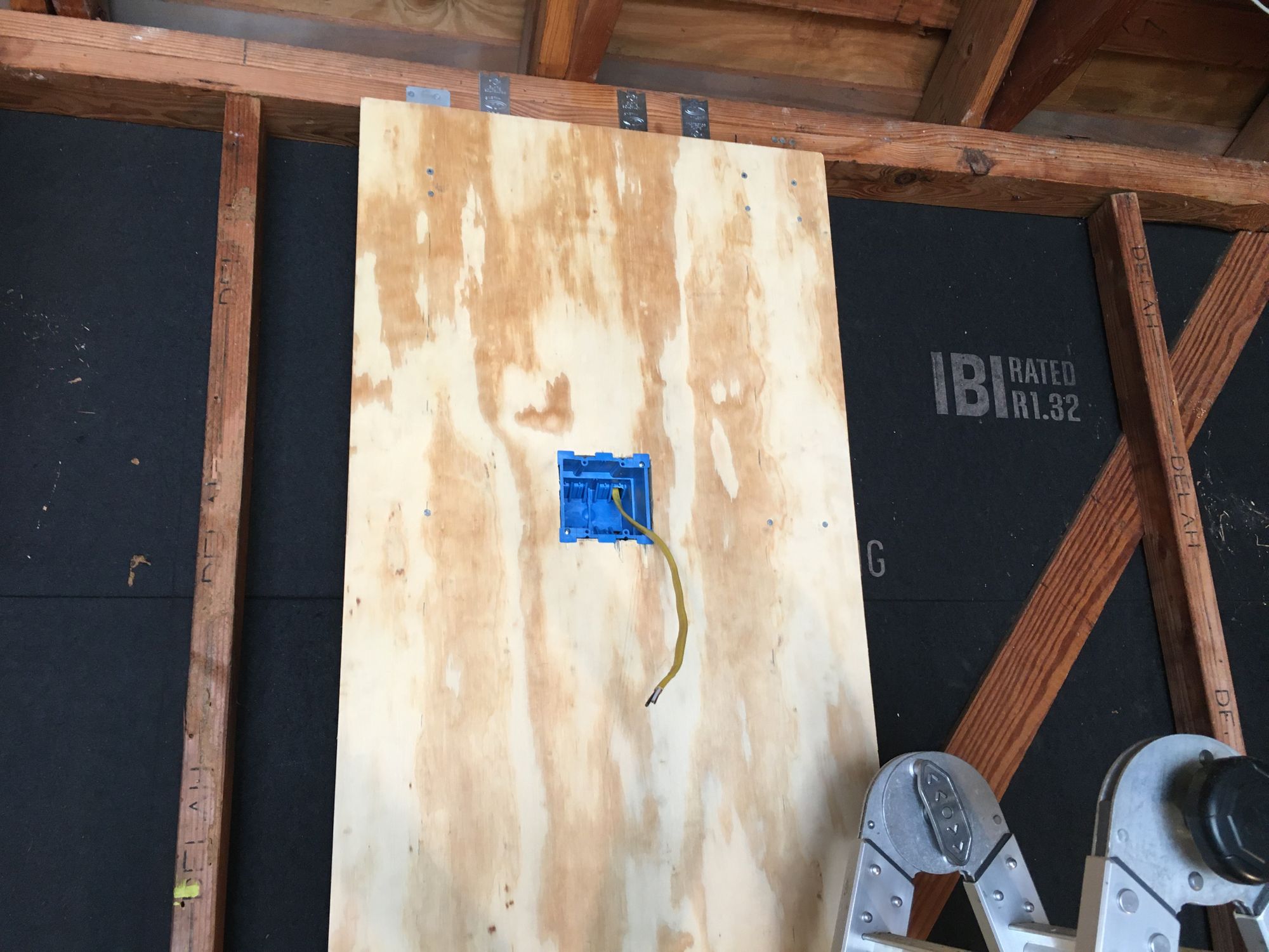
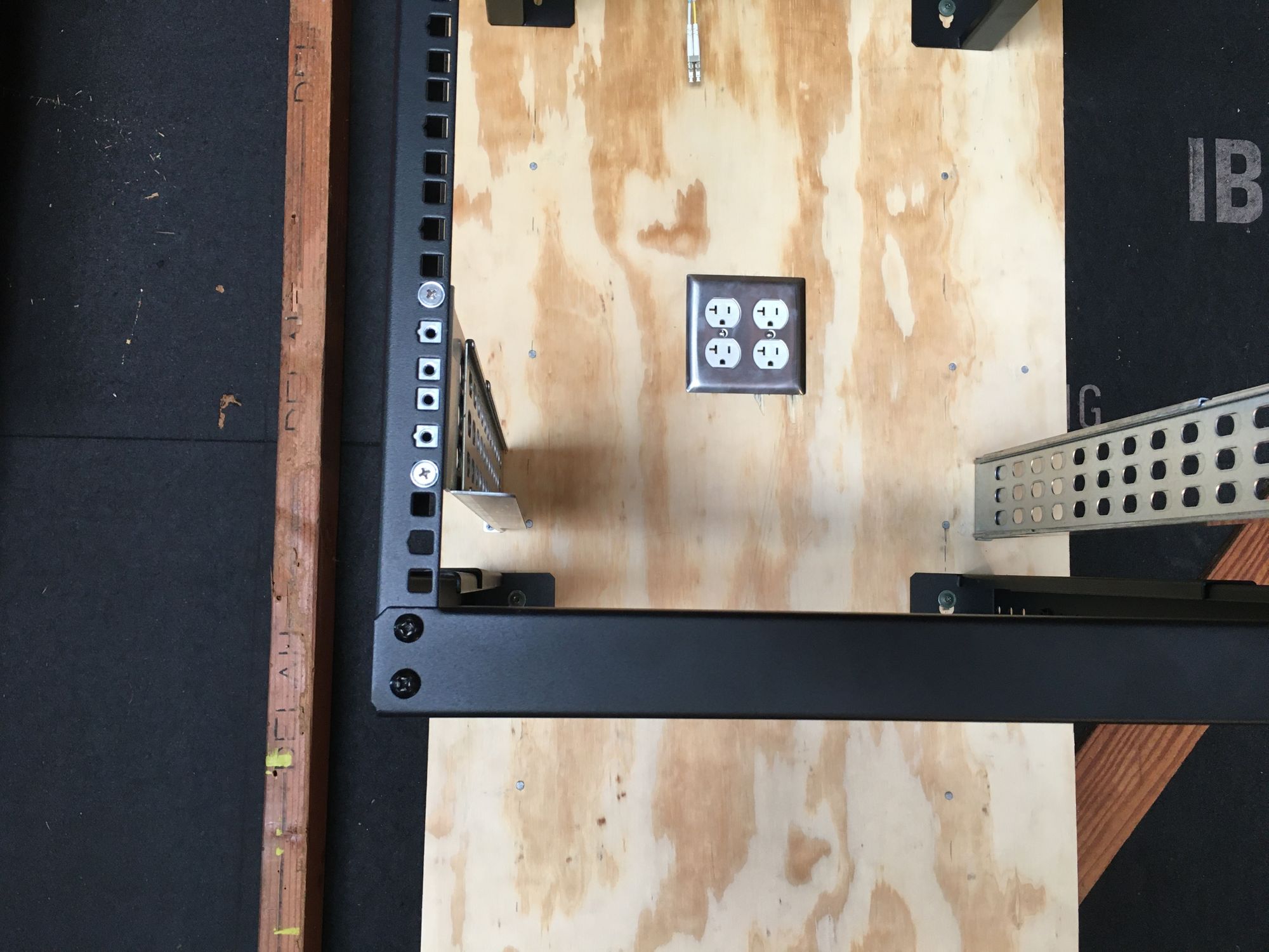
Here it is with the receptacles installed. I really don't like the white faceplate so I will swap it out later
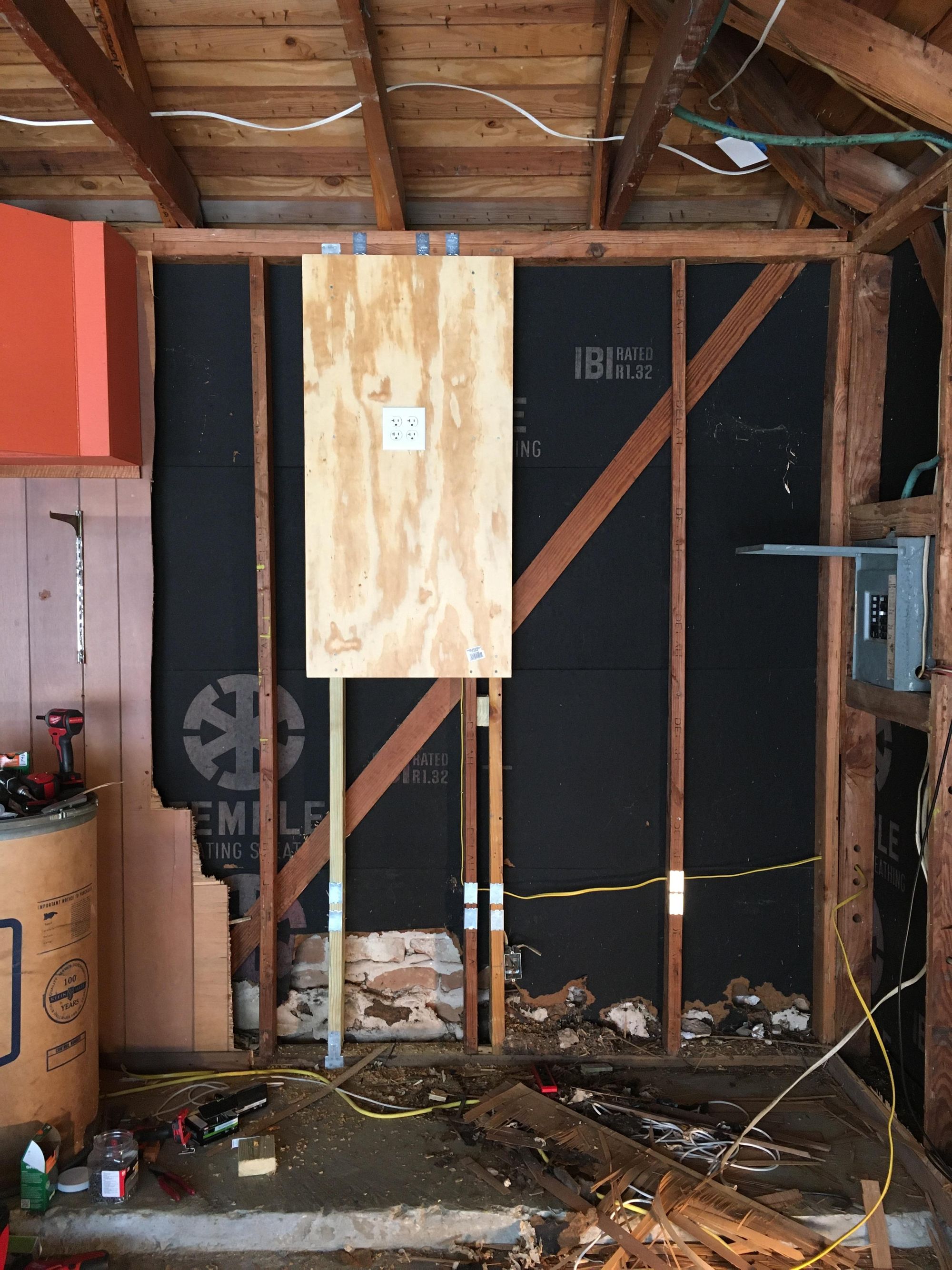
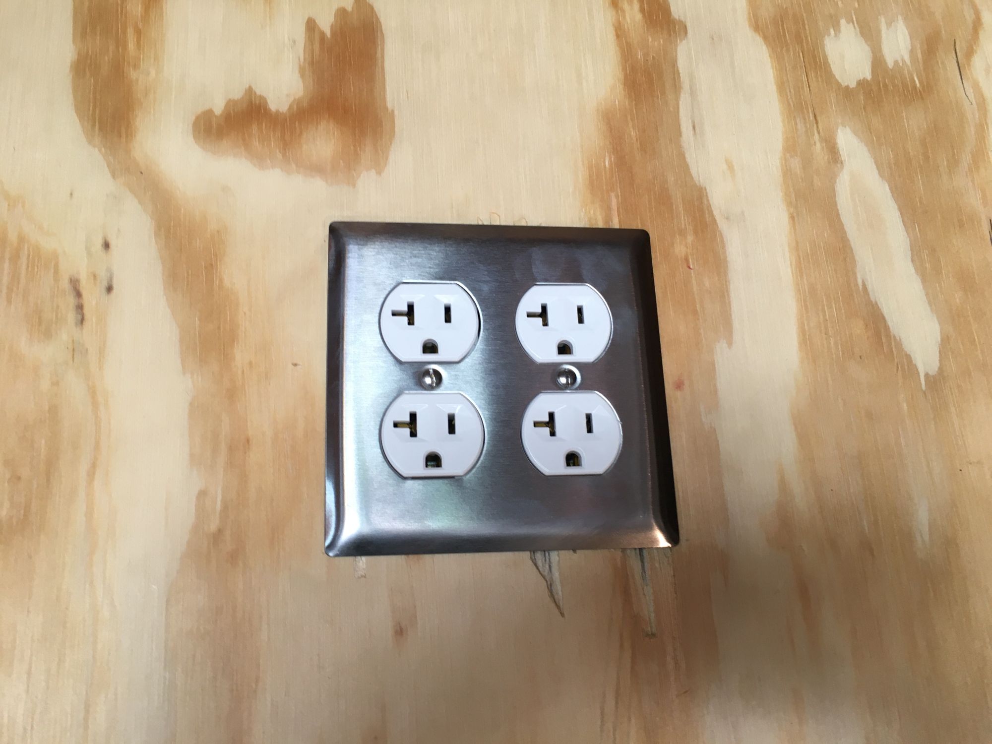
New faceplate, much better! I used 20a receptacles because its a 20a circuit, may as well...
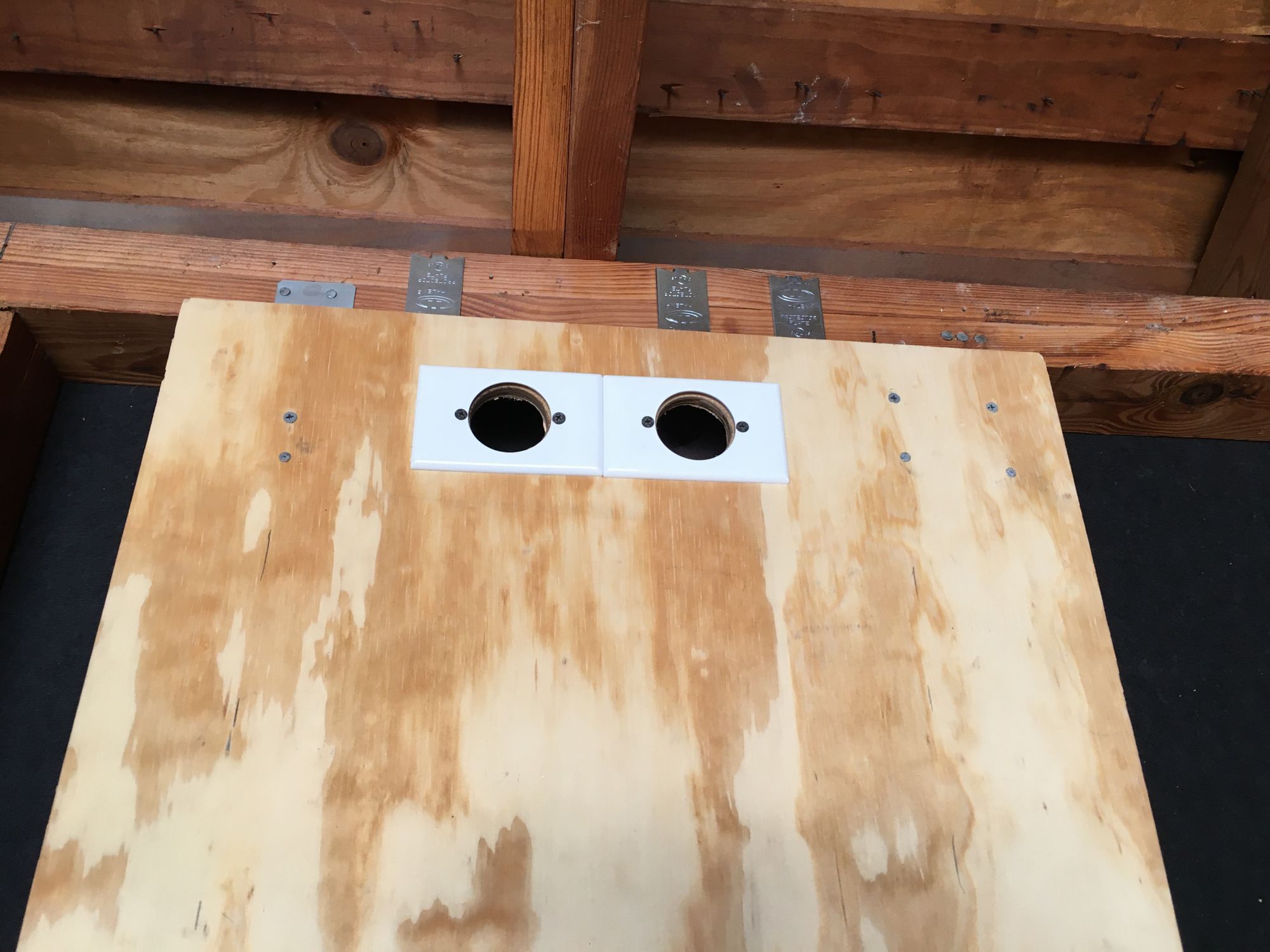
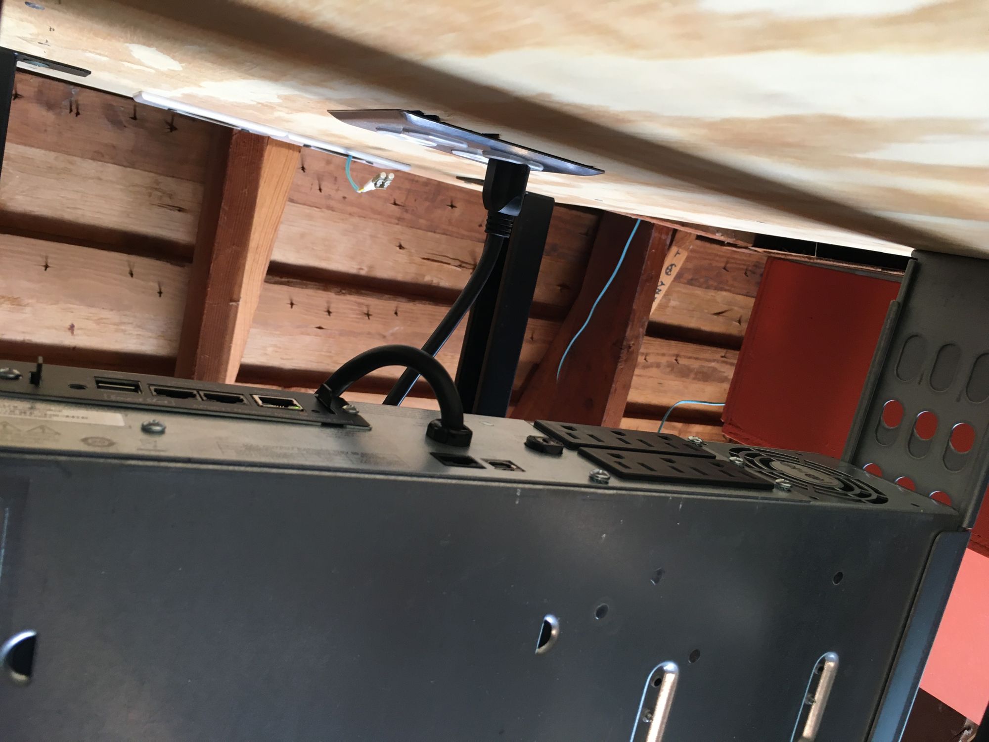
Next I drilled some holes at the top for cables to route though. Brush plates were over $5 each which is crazy, so I used these 60c dryer outlet plates
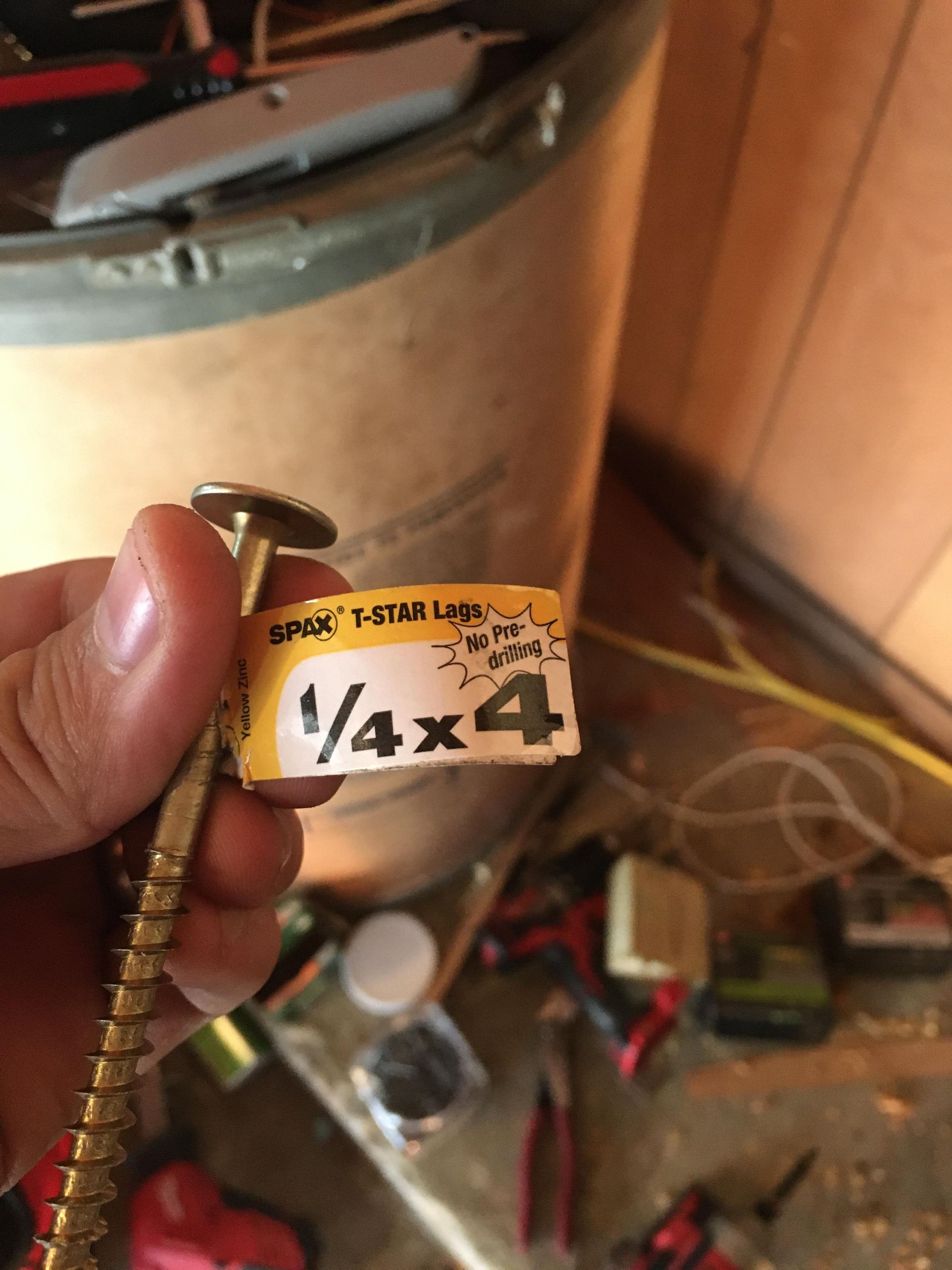
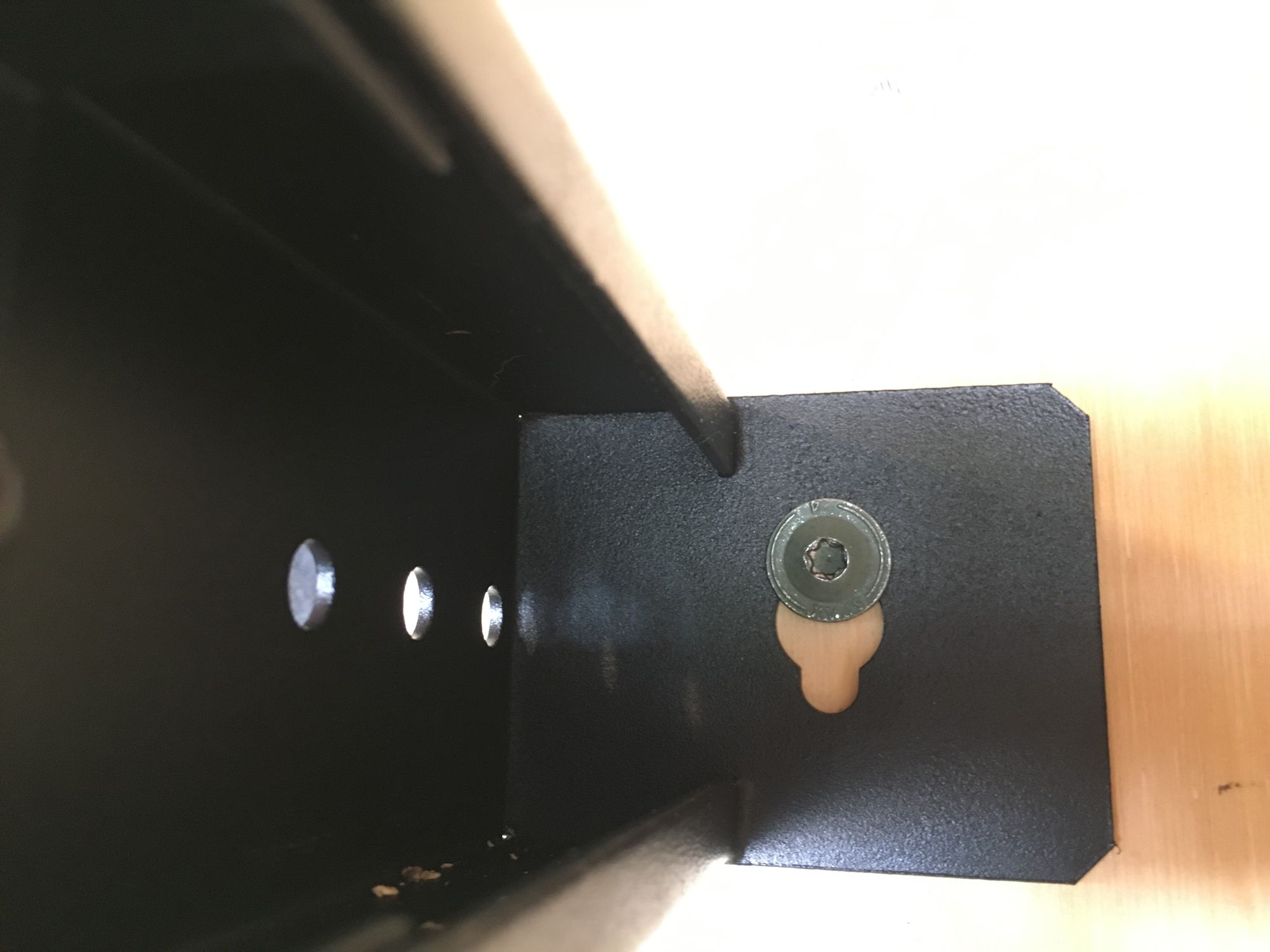
Next to mount the rack, I used these 1/4 x 4 SPAX Screws. They are awesome
Rack mounted! I can do pullups on the rack so its not going anywhere
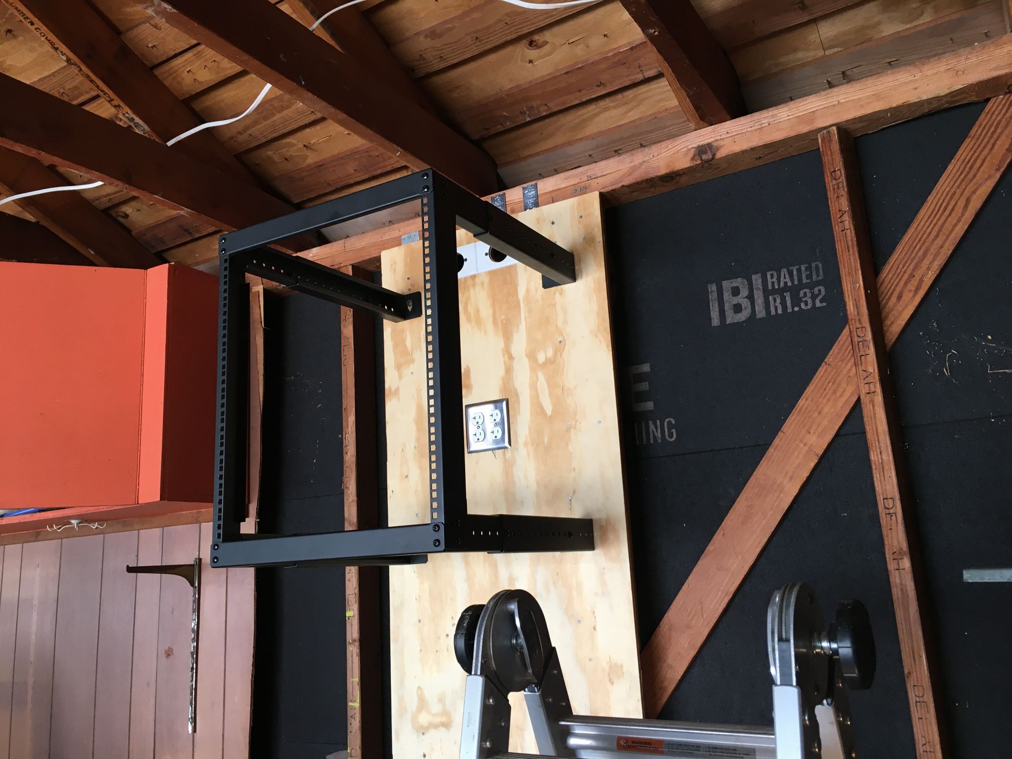
The hole were JUST big enough for the screw heads if I got them in at an angle, took some wiggling
I fished the fiber into the rack
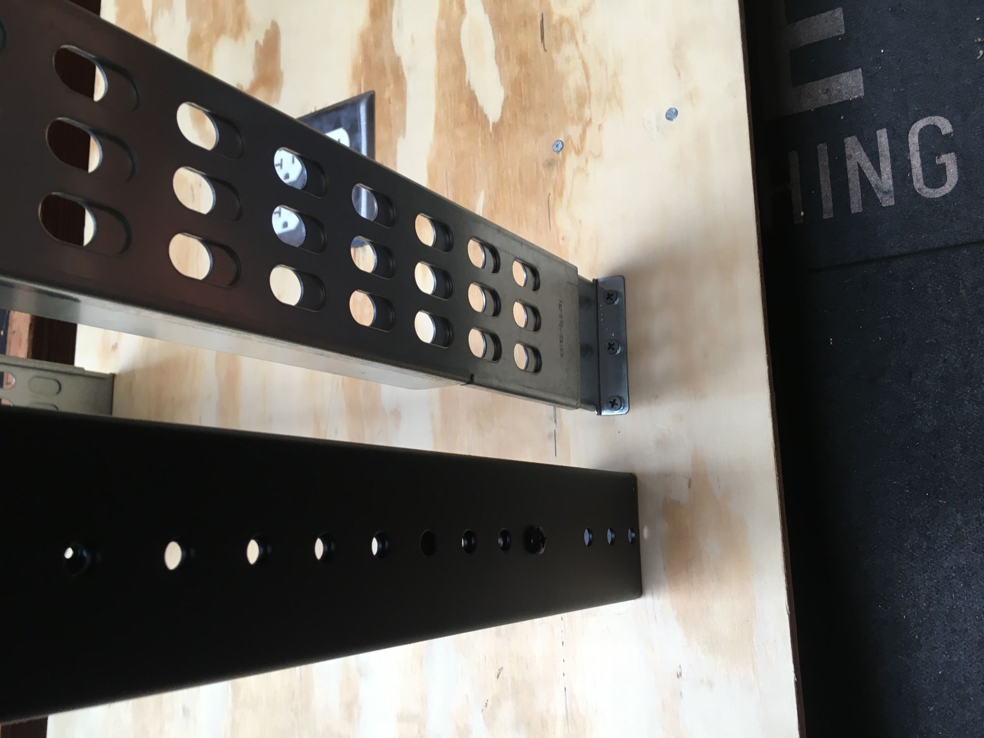
Next to get the UPS mounted. Sadly the bottom U of the rack has some clearance issues, so I wasted the bottom 1u
Since its not a 4 post rack I just screwed the rails into the plywood at the back, works great
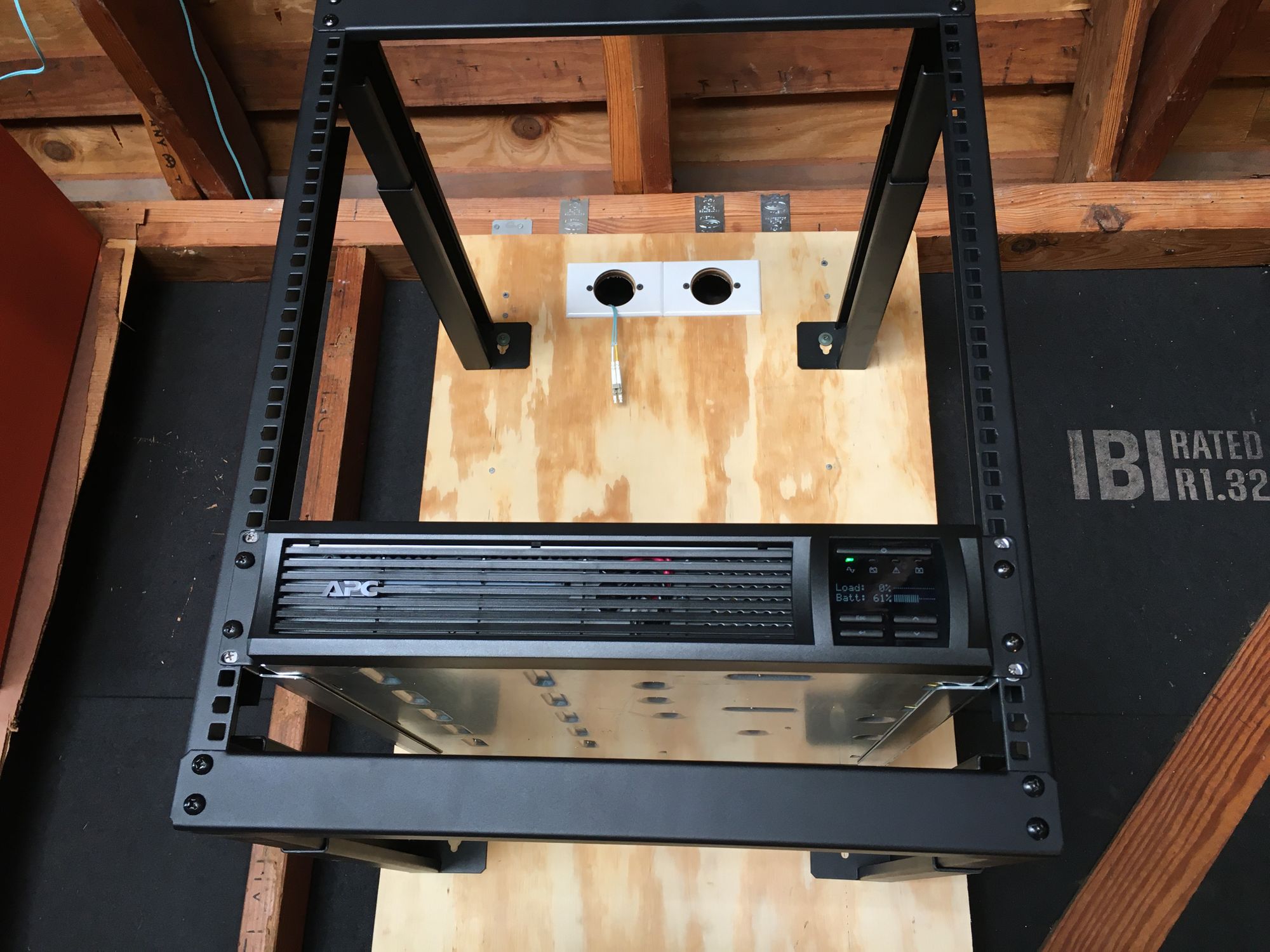
I installed the outlets in just the right place, and I made sure the rack was extended enough to have a lot of clearance
I got the switch mounted, I left 1u at the top for a patch panel
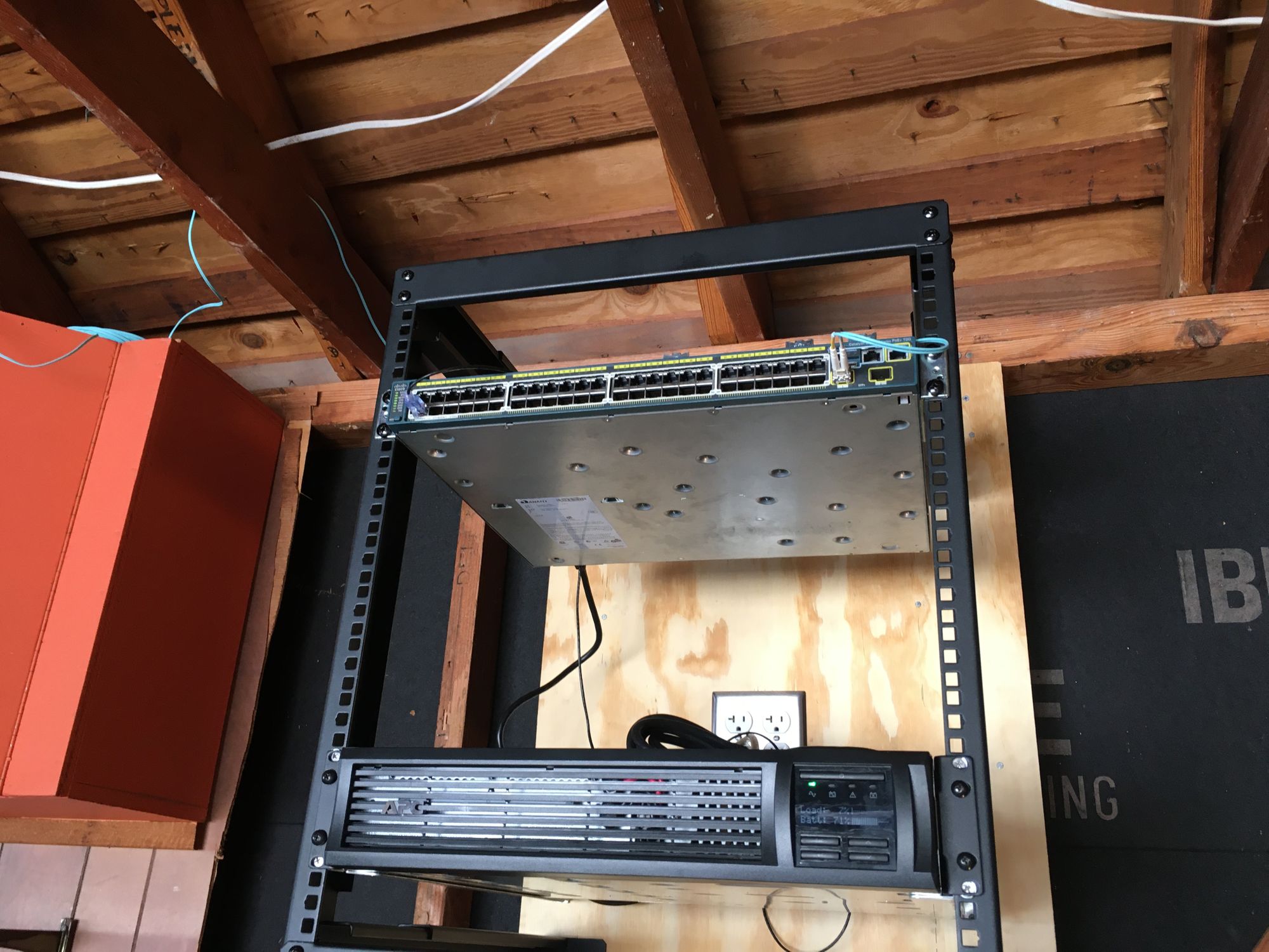
Got the blanking panel installed
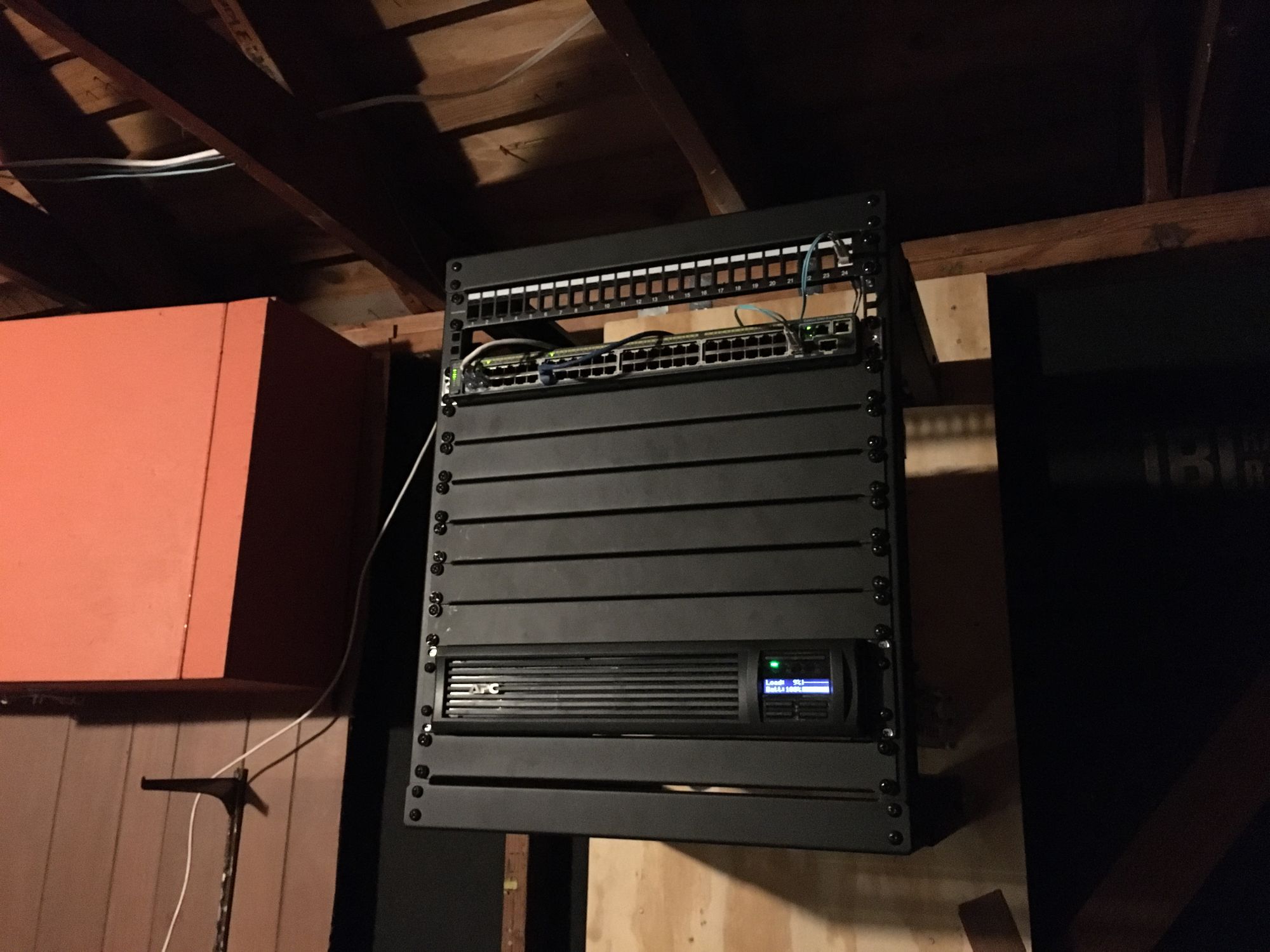
All done!